Spitfire Backup Circuits Advice
This guidance intends to offer an overview of how to connect and test backup services offered by Spitfire. As referenced within our Service Level Agreement, it is the Customer’s responsibility to ensure backup solutions are tested on a monthly basis by whoever has responsibility for their IT, that any backup solutions work as expected, and that the Customer’s staff understand how to effect any required failover. If you do not currently have a Spitfire backup solution please contact your Spitfire Account Manager!
See also DSL Information Sheet, FTTP Information Sheet and Ethernet Circuit Information.
Spitfire supplied and maintained routers will often be pre-configured and as such will be “Plug and Play”.
All information is believed to be correct at the time of writing. Some setups may differ depending on how they are configured. If you are unsure, please contact Spitfire Support for advice.
Manual Failover
General Information
This will typically be implemented on DSL circuits. You will know whether your circuit is setup for manual failover as the Wide Area Network (WAN) IP addresses will be the same for both the Primary and Backup internet services. These will typically be provided via different wholesale backhaul networks for resiliency and each circuit will often be provided with its own router. Refer to the Connection Details supplied with the purchased equipment for more information on IP Addressing details.
To failover, you will need to physically disconnect the Primary router from the Network Termination Equipment (NTE) and then connect the Backup router to its associated NTE. You will need to also move your LAN so that it is connected to the Backup router and wireless clients may also need to re-connect. You should not have both circuits connected at the same time. Details on which NTE to use can be found in the Connection Details document.
Where a service is mission critical, it is recommended that you brief the relevant person(s) on site with how to do this and where the relevant equipment is located. It is recommended testing be carried out on a monthly basis.
Automatic Failover
General Information
There are many different types of automatic failover available. Depending on which one is selected, there are different requirements for connecting. Testing each service is effectively the same procedure. You would just need to simulate a failure on the Primary by either disconnecting a cable or powering down the router. The most typical implementation of automatic failover, Fibre Ethernet and a DSL backup, are detailed below.
NOTE: The below examples are relevant for the majority of solutions but may not be applicable to some setups. For further details on other services types, please review our Ethernet Circuit Information document or contact Spitfire Support for guidance.
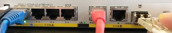
Cisco C1117-4PM (BTW FTTC Ethernet, VDSL or ADSL Backup)
Checking Setup is Correct
Ensure that an RJ11 cable is connected from the DSL port on the Cisco router into the DSL socket (using a DSL micro filter if the socket is not already pre-filtered - please refer to the DSL Information Sheet if unsure).
• A solid CD light indicates that there is sync between the Cisco router and the DSLAM in the exchange.

• A flashing CD light indicates that the router is trying to sync but has not been successful. Check to make sure that the cable is correctly plugged in at both ends and that it is connected to the correct line. Please contact Spitfire Support and raise a support case if the line still does not sync.
Operational Test
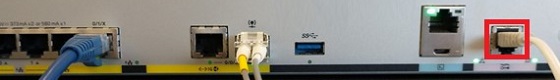
Remove the fibre/copper cable from WAN port G0/0/0. This will stop traffic routing over the primary connection.

• Traffic should now start routing over the backup.
Note that it can take up to 3 minutes for the switchover to take effect.
Juniper SRX340/320 (BTW FTTC Ethernet, VDSL or ADSL Backup)
Checking Setup is Correct
Ensure that an RJ11 cable is connected from the DSL port on the Juniper router into the DSL socket (using a DSL micro filter if the socket is not already pre-filtered - please refer to the DSL Information Sheet if unsure).
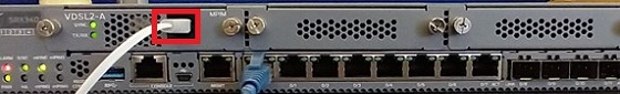
A solid SYNC light indicates that there is sync between the Cisco router and the DSLAM in the exchange.

A flashing SYNC light indicates that the router is trying to sync but has not been successful. Check to make sure that the cable is correctly plugged in at both ends and that it is connected to the correct line. Please contact Spitfire Support and raise a support case if the line still does not sync.
Operational Test
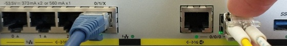
Remove the cable from G0/15 (fibre terminations) or G0/7 (copper terminations). This will stop traffic routing over the primary connection.

• Traffic should now start routing over the backup.
Note that it can take up to 3 minutes for the switchover to take effect.
Cisco C1111-4PM (TTB FTTC Ethernet, Ethernet Backup)
Checking Setup is Correct
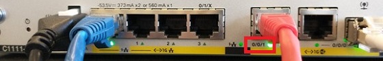
Ensure that an RJ45 crossover cable is connected from G0/0/1 on the Cisco router into the Ethernet NTE.
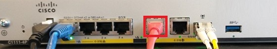
• A solid LINK LED underneath the port indicates that there is a physical link between the Cisco router and the NTE.
• If the LINK LED is off then make sure the cable is correctly plugged in at both ends or try an alternative cable. Please contact Spitfire Support if this does not resolve the issue.
Operational Test
Remove the fibre/copper cable from WAN port G0/0/0. This will stop traffic routing over the primary connection.

• Traffic should now start routing over the backup.
Note that it can take up to 3 minutes for the switchover to take effect.
Juniper SRX340 (Ethernet/TTB FTTC Ethernet Backup) for the Primary and Backup delivered for RJ45 interface
Checking Setup is Correct
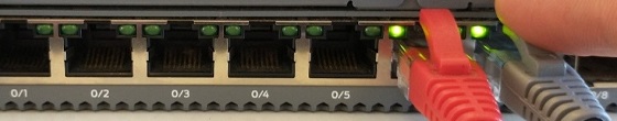
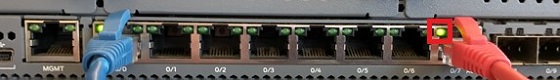
Ensure that an RJ45 crossover cable is connected from G0/6 on the Juniper router into the Ethernet NTE.
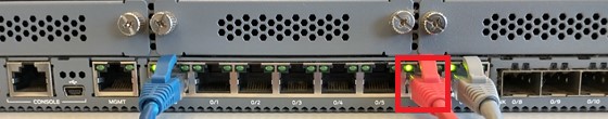
• A solid LINK LED (left of the port) indicates that there is a link between the Juniper router and the NTE. A flashing ACT LED (right of the port) indicates that there is activity on the link.
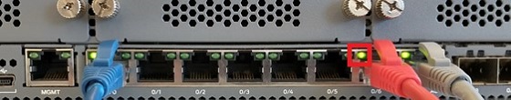
• If the LINK LED is off or there is no activity on the ACT LED then make sure the cable is correctly plugged in at both ends or try an alternative cable. Please contact Spitfire Support if this does not resolve the issue.
Operational Test
Remove the cable from G0/7. This will stop traffic routing over the primary connection.
• Traffic should now start routing over the backup.
Note that it can take up to 3 minutes for the switchover to take effect.
Juniper SRX340 (Ethernet/TTB FTTC Ethernet Backup) for the Primary delivered using LC interface and the Backup delivered using RJ45
Checking Setup is Correct
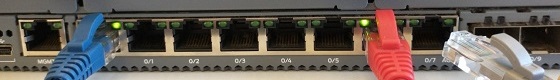
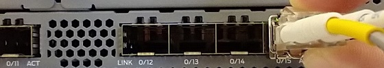
Ensure that an RJ45 crossover cable is connected from G0/7 on the Juniper router into the Ethernet NTE.
• A solid LINK LED (left of the port) indicates that there is a link between the Juniper router and the NTE. A flashing ACT LED (right of the port) indicates that there is activity on the link.
• If the LINK LED is off or there is no activity on the ACT LED then make sure the cable is correctly plugged in at both ends or try an alternative cable. Please contact Spitfire Support if this does not resolve the issue.
Operational Test
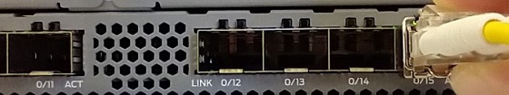
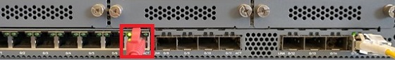
Remove the cable from G0/15. This will stop traffic routing over the primary connection.

• Traffic should now start routing over the backup.
Note that it can take up to 3 minutes for the switchover to take effect.
First Hop Redundancy Protocol Automatic Failover
The most straightforward implementation would be comprised of a Layer 2 switch connecting the two routers before your Local Area Network (LAN) equipment, so that the two routers can communicate. This will not work by connecting the two routers directly to each other.
You would simply connect the appropriate interface on the router to the L2 switch, and then connect the switch to your LAN. You can test this by simply removing the cable from the WAN interface of the Primary router. The backup will assume priority and assume the role of the primary. Other implementations are possible. The most important factor is that the two routers have a method to communicate.
Other Historic Solutions
General Information
Technicolor Router to “bridge” DSL over to the primary. This is no longer a solution we recommend. You should consider speaking with your Spitfire Account Manager to enquire about other, more modern solutions.